MikroTik Packet Flow, Firewall Chains

The next topic that I want to speak about Packet Flow then about Firewall Chains.

It is very important to understand how the packet flows inside the MikroTik RouterOS device once it enters the device. There is a lot of confusion about this topic, and I can say that most engineers have a problem understanding this topic. For this reason, I will make it as simple as possible to let you understand how the packet flows inside the MikroTik RouterOS device.

Let’s see the diagram of the packet flow on the MikroTik RouterOS as provided by MikroTik company:

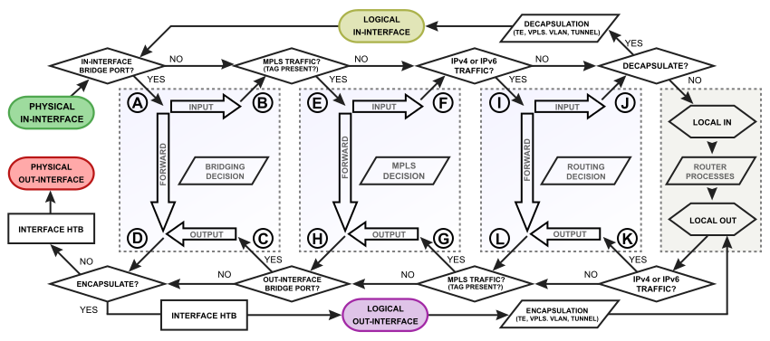
Look at that, this is how the packet flows inside the MikroTik RouterOS device. Is it clear for you ????? I do not think so, right? Don’t worry, it was not clear for me at the beginning before I did some research to understand it well and now being able to explain it to my students.

As you can see, the packet flow consists of 4 main boxes which are:

  • Bridging box
  • MPLS box
  • Routing box
  • Local Process box

To make the picture clearer for you, I have made the below illustration:

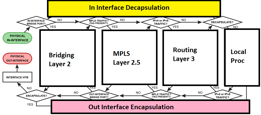
Now it looks much better. So, I know that the 1st box of the left is for bridging, the 2nd is for MPLS, the 3rd is for Routing and the last one is for Local Processing.

On top we have the decapsulation of the packet when it comes inside the MikroTik device, and on the bottom we have the encapsulation when it is leaving the MikroTik device out of one of its interface.

Now I think it is clearer for us, and we know (for example) that routing process happens on box 3, bridging happens and box 1 and so on.

To make even clearer, let’s remove the MPLS box because in this book we have nothing to do with MPLS. Let’s see how the packet flow illustration would look now:

[mepr-show rules=”319″ unauth=”message”]

This makes the look for the packet flow diagram much simpler than the 1st picture that we have seen.

Now I will take the Routing box by itself and see what is consists of:

This is exactly what the Routing box consists of. You can see inside of it:

  • Input
  • Forward
  • Output
  • Routing decision

This routing box has some routing subprocesses. Let us see them:

Excellent! This makes more sense from where the chains input, output, forward and so on are coming when we do rules on the firewall. But what I see here also some IPSEC subprocesses inside the routing box. I decided to remove them completely to make the routing subprocesses even simpler:

Now the routing box looks much simpler. Now we know from where the chains on the firewall are coming from.

Every one of those Layer 3 chains has also a subprocess. Let’s see them here:

This is really what I want to see. Meaning that when the packet enters the routing box, it goes 1st to the Prerouting chain. In this prerouting chain I can do the following on the packet:

  • Hotspot-in
  • Raw prerouting
  • Connection tracking
  • Mangle prerouting
  • DST-NAT

Then the packet will leave the prerouting chain and go to the routing decision. Once routing has happened, and if the packet is going to the router itself, then it will go to the input chain where you can do the following there:

  • Mangle input
  • Filter input
  • HTB Global
  • Simple queues

And it continues this way until it leaves the router.

This means to me that if I want to treat the packet as soon as it reaches the routing process, the 1st thing I can use is the prerouting chain on the firewall.

We are done with the routing box. Let’s check now the bridging box:

This is what this box looks like. Again, the bridging box has some sub-processes which can be determined as the following:

Also, in bridging there is firewall, but it is layer 2 firewall. Also, you can see the chains that can be used in the bridging firewall. There is possibility of Layer 3 firewall in bridging, but I will remove it because if I want to use Layer 3 firewall then I will use the one in the routing box.

Finally, I want to put everything in one picture and apply 1 example to see how the packet will be flowing:

This is how it will finally be represented.

Let’s make 1 example to see how the packet will be flowing inside the MikroTik RouterOS device.

Packet Flow Example

I have a MikroTik router, and my PC is connected to its interface on Ether5. I am doing a ping to the router itself, meaning that the ICMP ping message is getting inside the router on the interface Ether5 and leaving from Ether5 when my PC receives a ping reply.

Let’s see how the packet will be flowing and where we can apply firewall rules and on which chain:

1st it will enter inside Ether5, then it will be asked whether Ether5 is part of a bridge. In our case Ether5 is not part of a bridge, then it doesn’t go to the bridging box and will continue:

Prior entering the routing box, it will be asked if it is an IPv4 or IPv6 traffic. In my case it is, then it will enter the routing box.

The 1st chain it reaches to is the Prerouting chain. Now you can check what you can do on the prerouting chain as we have seen before:

Let’s see what will happen next:

Then It will go to the Routing decision, and here it will be asked if it is going to leave from the same interface or from another interface. In another way to explain, is the traffic coming to the router itself or passing via the router? In my case, I am doing ping to the router itself, then it will send it to the input chain:

Once it reaches the input chain, now we can see what we can do with this packet as for the firewalling:

Let’s say we did not do anything on the input chain, let’s see how it keeps moving:

It leaves the routing box, the packet will be processed on the router processes, then it will be asked again if it is an IPv4 or IPv6 packet. In our case yes, it is, then it will enter to the routing box again:

Once it enters the routing box, its passes via the routing decision then to the output chain. There again you can decide what you can do with this packet based on the subprocess in that chain:

If nothing happens, it will continue it way and reach to the Postrouting chain:

Also, on the postrouting chain you have many subprocesses:

After finishing from the postrouting chain, it will leave the routing box and will be asked again if it is going to a bridge interface (which in my case it is not), meaning that it will not enter to the bridging box, then it will go to interface HTB where you can apply QOS before it leaves out from the interface Ether 5:

This what exactly happens to the packet when it is flowing inside the MikroTik RouterOS. I hope with this explanation the idea is clearer for you, and you know from where the chains come and what you can do on each chain.

In the upcoming point, I will explain about the Firewall RAW.

[/mepr-show]

0 Comments

Submit a Comment

Your email address will not be published. Required fields are marked *


The reCAPTCHA verification period has expired. Please reload the page.

Please Login to Reply or add a comment!

About