Configuring OSPF on Huawei

In this chapter, I will do a LAB to show you how to configure basic OSPF on the backbone area. The whole idea of this chapter is to make you familiar with the OSPF configuration CLI on Huawei and to show you how OSPF would discover the remote networks once it is enabled on all routers.

Let’s get started.

LAB: Configuring OSPF

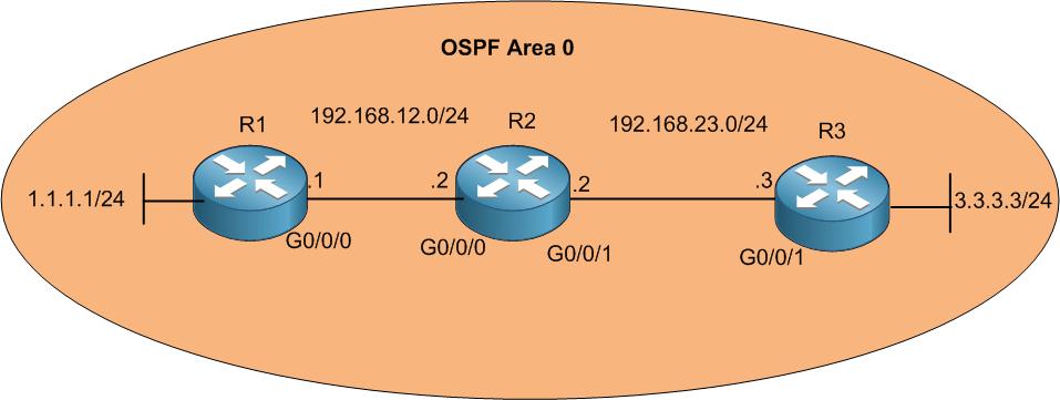
In this LAB, we have 3 routers connected to each other (R1 to R2 and R2 to R3) via Gigabit Ethernet interfaces. The main goal is to allow the end device at R1 LAN, which is 1.1.1.1/24, to be able to reach the end device at R3 LAN, which is 3.3.3.3/24.

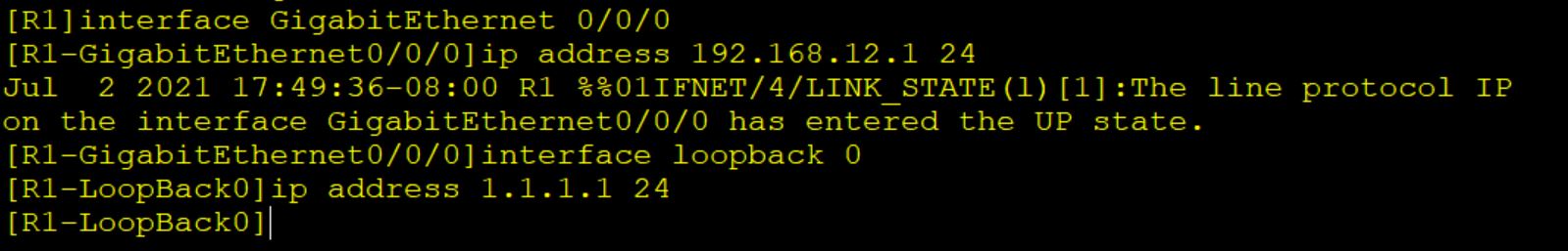
For the moment I only have those devices connected to each other. Let’s start 1st by adding the IP addresses as on the scenario. Will start from R1, then R2 then R3.

[mepr-show rules=”319″ unauth=”message”]

Here I have configured the IP addresses on all 3 routers. You can see that I have used a loopback interface on R1 to represent the network 1.1.1.0/24 and another loopback interface on R3 to represent the network 3.3.3.0/24.

Let’s start configuring OSPF on R1 then I do on R2 and R3.

Let me explain to you what I have done here. 1st I need to enable OSPF process, for this I have written OSPF. I could put after “ospf” a process id which is just a number, but on Huawei it is not mandatory,

Then I have mentioned that this router will be in area 0. You will see that it goes to area 0.0.0.0 which is the same as area 0 (the area consists of 32 bits same like the IP address). Afterward, I need to advertise the connected networks into OSPF. On R1, the 2 networks that are connected to it are:

  • 192.168.12.0/24
  • 1.1.1.0/24

The big question that most of students ask is: what is the 0.0.0.255?

This is the wildcard mask. The wildcard mask can be calculated based on the subnet mask of the network. For example, in our scenario, the subnet mask of both connected networks is: 255.255.255.0 (/24). From this, I can get the wildcard mask. The calculation is just so simple. You write 255.255.255.255 and you subtract from it the subnet mask, then the result is the wildcard mask. Let me show you how this can be done:

255 255 255 255
Minus (-) Minus (-) Minus (-) Minus (-)
255 255 255 0
0 0 0 255

That is all you need to do to get the wildcard mask. That’s why you see that the wildcard mask on both networks is 0.0.0.255.

We are done on R1, let’s configure OSPF on R2.

Once you configure the OSPF on R2, you will see that a neighborship will be formed with R1 and you will get a notification on your console as the following:

Let’s check with a command whether the OSPF neighborship has been truly created between R1 and R2:

With the command “display ospf peer” you can check who is the OSPF neighbor with R2. It is clearly that R2 has formed neighborship with R1 who has the router-id 192.168.12.1 (will speak about router id in a moment), the state is full and the neighbor is up since 3min 59 seconds.

As the neighborship is formed, then R2 should know about R1 network which is 1.1.1.0/24 from OSPF. Let’s check.

Look at that ???? – R2 knows about R1 network which has an IP of 1.1.1.1 – that’s really nice. So now R2 can reach it. Let’s try to ping it from R2.

Excellent, the ping is working without any problem.

Let’s continue our OSPF configuration because our goal is to allow the network of R1 to reach R3’s network and vice versa. For this moment, R1’s network cannot reach yet R3’s network (& vice-versa), and if you want let me issue a ping from R1’s network to R3’s network:

As you see, I have issued a ping from R1 having a source of 1.1.1.1 to the destination IP 3.3.3.3 and I do have a failure. For this to work, we need to configure OSPF between R2 and R3 so the neighborship is form. We have already configured OSPF on R2, let’s do now on R3.

Once this is configured on R3, I got a notification on the console that the neighborship with R2 is full as you see below:

By doing so, all 3 routers have OSPF configured, that means that they have informed each other about their networks and the routers which don’t know about any of the advertised networks will be adding them in their routing table. For us, the most important it to know whether the 3 routers know about the following 2 networks:

  • 1.1.1.0/24
  • 3.3.3.0/24

We start from R1 which surely knows about 1.1.1.0/24 because it is connected directly to him, but what about 3.3.3.0/24 network? Let’s check R1 routing table.

Indeed, R1 knows about 3.3.3.0/24 network from OSPF.

What about R2? If we think logically, R2 should learn about the 2 destination networks from OSPF because they aren’t directly connected to him. Let’s check his routing table:

Yes!!!! He can see both networks from OSPF.

Finally, R3 has 3.3.3.0/24 directly connected to him, so he should learn about 1.1.1.0/24 network from OSPF. Let’s check the routing table of R3:

Indeed, he has learned from OSPF about the destination network on R1 which is 1.1.1.0/24.

All looks well for now. Let’s issue then the ping from R1’s network to R3’s network which wasn’t working before and see if it will work now.

Here we go, it is working ????

What if we issue the ping from R3’ network to R1’s network? Let’s try:

Excellent, it is working also. So, the way we configured OSPF is doing the job ????

P.S: Leave this LAB operational because we need to use it in the upcoming LAB.

[/mepr-show]

0 Comments

Submit a Comment

Your email address will not be published. Required fields are marked *


The reCAPTCHA verification period has expired. Please reload the page.

Please Login to Reply or add a comment!

About