What is OSPF Summarization and how to configure it on Huawei?

OSPF summarization (also sometimes referred as aggregation) is a way to make a summary address for different networks which are in an area, so a summary address will be representing all those routes in the other area. This is one of the functions of the ABR.

Summarization cannot happen inside the area itself, something that you should always remember.

Also, summarization can happen on the ASBR for LSA type 5.

In a conclusion,  summarization can happen on LSA type 3 and 5.

But why we need to do summarization? It is just to reduce the processing on the routers and the memory usage. Then instead of each router has many entries in his routing table to many networks, he will have only 1 representing all of them.

It is not clear for you the idea yet? That’s normal and don’t worry. With the LAB now you will understand better.

I still have the LAB of the last chapter open, let’s see what we need to do.

LAB: OSPF Summarization

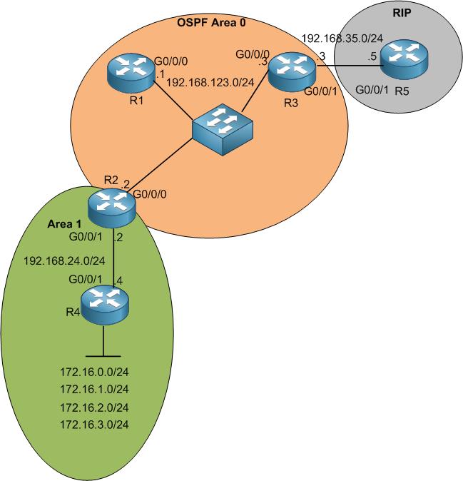
As you see, we are still in the same scenario. The only change is that I have now 4 networks connected on R4 (I created loopback for each one) that need to be advertised into OSPF. This way, each router will have 4 entries in his routing table for those 4 networks.

[mepr-show rules=”319″ unauth=”message”]

Let me advertise them into OSPF on R4. I will use only 1 command to advertise the whole 4 networks into OSPF.

This way, I have the 4 networks advertised into OSPF using 1 command.

Let’s check if R2 (in area 1), R1 (in area 0) and R5 (in RIP) can see all 4 networks in their routing tables.

On R2, I can see all the networks inside its routing table.

Let’s check on R1, which is in area 0, if he can also see all the networks.

Indeed, they are showing up on R1’s routing table. Just for fun, let me show you the LSDB table on R1 then you can see that those networks will be on LSA type 3.

Finally, let’s check R5 routing table and see if he can see all those networks as well as RIP.

Here we go, they show as RIP because R3 is importing the OSPF networks to RIP from the last LAB.

Everything looks fine for me. However, you can see that each router is occupying 4 entries in his routing table, and this takes memory usage. Also, we saw that the 4 networks are in the LSDB tables of the OSPF routers, that means that once the SPF algorithm has to run it will take longer time to get the best routes to the destinations and this will put load on the routers’ CPU.

Of course, you may say that those are only 4 entries so not a big deal – I somehow agree with you. But what if we have 50 entries of more? Isn’t it better that we can do a summary address for all those networks then only 1 summary address can represent them?

If we look to the networks, they have similarity as following:

  • 172.16.000000 00.x
  • 172.16.000000 01.x
  • 172.16.000000 10.x
  • 172.16.000000 11.x

You can see that the 1st and the 2nd octet are the same for all 4 networks. In the 3rd octet, the first 6 bits are always the same. The change is happening from bit 7 at the 3rd octet onward.

In this way, I can count the bits that are not changing then I can get the new subnet mask for the summary address.

We have: 8 bits (1st octet) + 8 bits (2nd octet) + 6 bits (3rd octet) = 22 bits

Then the subnet mask in this case will be: 255.255.252.0

What about the network ID representing the 4 networks? Here we should check which numbers in the IP part are not changing. We see that 172.16.0.x are the numbers that are not changing. Then then network ID for this summary address will be: 172.16.0.0

In conclusion, the following summary address will represent the 4 networks:

172.16.0.0

255.255.252.0 (/22)

Excellent!!!! We have now the summary address of the 4 networks.

Now where and how to apply.

The route summarization happens only on the ABR in OSPF, and on the ASBR in case you want to make a summary address for RIP networks for example.

In our case, it should be applied on the ABR which is R2. Let me show you how this can be done.

This is done. I have applied the summary address that I have calculated on R2 which is the ABR.

Let’s check now if R1 and R5 will see the summary address replacing all the 4 entries that were in their routing tables.

Here it is ???? – Excellent!!!!

Out of curiosity, let’s check the LSDB table on R1 also.

Also, the summary address is showing up in the LSDB table of R1 in place of the 4 networks. That’s really great.

Let’s check R5 what he will see in his routing table.

Also, R5 sees the summary address instead of having 4 entries for the 4 advertised networks. That’s awesome.

Now if you try to reach any of those 4 networks from R5 for example, he will use the summary address in his routing table to route the traffic to the destination network and he will be able to reach them.

I will show you that my pinging 172.16.1.4 and 172.16.2.4 which are 2 loopbacks in R4 and see if R5 can reach them.

Excellent!!!! Both pings are working ????

This is all what I wanted to show you in this chapter, hope you enjoyed it and please leave the LAB open for the upcoming chapter.

[/mepr-show]

0 Comments

Submit a Comment

Your email address will not be published. Required fields are marked *


The reCAPTCHA verification period has expired. Please reload the page.

Please Login to Reply or add a comment!

About