Another important topic is the Management VLAN. You may have noticed that once you put a switch port on a VLAN then the PC connected to it will not be able to log into winbox of that switch. What if we have 80 MikroTik CRS3xx switches in our network, how will I be able to login to them to configure them? The best way is to use a Management VLAN.
The concept is very simple. You create a Management VLAN on each Switch under the bridge interface, you give an IP address to it then you advertise it on the VLAN as a trunk port on all the switch ports. From the PC side, you need to use the same VLAN on your network card (some old Network Interface Cards do not allow to add a VLAN ID on it), you put an IP address from the same range as you have put on the Management VLAN, then you will be able to gain access to the Switch(es) again.
I think you are lost now, right? No problem. Let’s do a LAB and with LAB you will understand it better.
LAB: Management VLAN
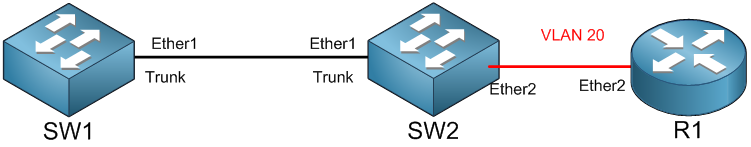
As you can see, I have 2 MikroTik CRS3xx switches connected to each other on the Ether1 interfaces. They have trunk ports. Then I have R1 (which is an end device) connected from its interface Ether2 to the Ether2 of SW2 which is on VLAN20.
This configuration is already done, and I will not repeat it because I have already explained how you can do trunk and access ports. Now the idea is that R1 will not see any more SW2 and SW1to be able to configure them (remember that R1 is like a PC). To be sure of that, I will put my PC in place of R1, and you will see SW1 will not be shown. In case I try to connect to SW2 then it won’t work.
Imagine you have a lot of switches in your network, and you have a problem with one of them that you should connect to it to solve the problem, but you cannot. This is not the best thing I would say, do you agree?
So, what options do we have here? Well, we need to create a Management VLAN on each of the switches which we will use when we want to connect to the switches.
Let’s start creating the Management VLAN on SW1 and SW2 and give them an IP from the range of 192.168.1.x/24
Let’s start with SW1:
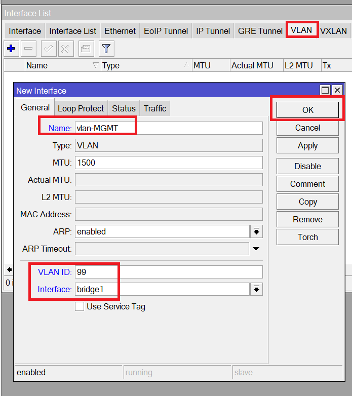
As you see, I have created a VLAN for management under the interface bridge1 and I have used VLAN ID 99.
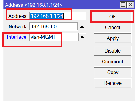
Now we need to give it an IP address:
Apologies, the Full Lesson Access is Only for Members....

Get Access to all Lessons from different Vendors
Affordable Price to Enhance your IT Skills!
Always Accessing all Lessons including the New Added Ones

100% Satisfaction Guaranteed!
You can cancel your membership at anytime.
No Questions Asked Whatsover!
0 Comments