Configure the normal Spanning-Tree Procotol (STP) on the MikroTik Switches

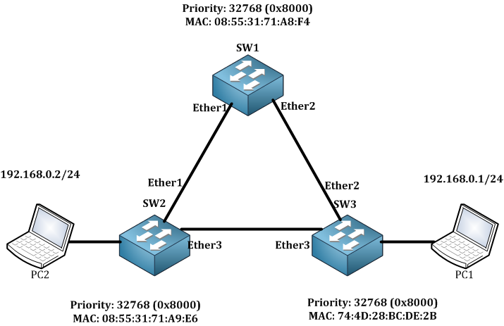
As you can see, this is my scenario. I have a redundant switch network and I want to use the classic STP to have a loop-free network.

I have already put the interfaces inside the bridge on all Switches. Remember, you should be on a version over 6.41 so the Switch chip Hardware offload would work. Also, when adding the interfaces to the bridge, be sure that you check the hardware offload.

By default on MikroTik, the Switches are using RSTP, so we need to change that to STP. You should go to each switch and from the bridge, you go to the STP tab and enable STP.

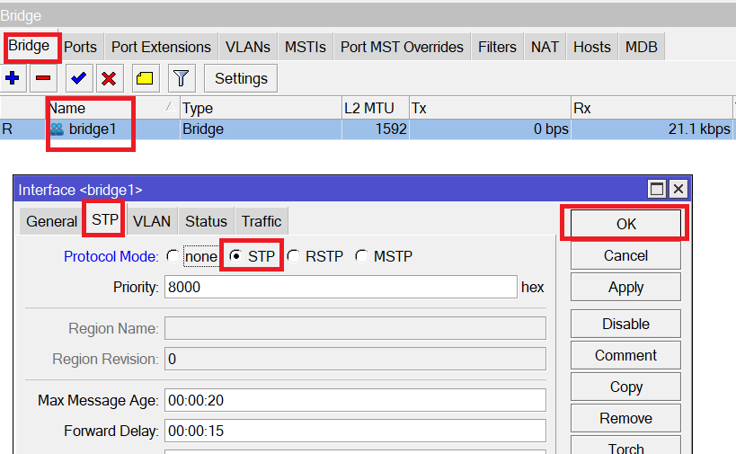
If you look carefully, the priority by default is 8000 on hexadecimal.

Now STP is enabled on all 3 switches. Excellent.

Let’s see which switch has been elected as a Root Bridge and check its port states. If we compare the Bridge IDs of the 3 switches, we see that SW1 has the lowest bridge ID, thus all its ports should be designated ports. Let’s check on SW1 itself.

[mepr-show rules=”319″ unauth=”message”]

Let’s see is SW1 ports are designated ones:

Excellent!!!! Both Ether1 and Ether2 are designated ports. Also, look at the letter “H” behind each interface which says that the interfaces are hardware offloaded.

Now we know which Switch is the Root Bridge, then the interfaces of the none-root bridge (SW2 and SW3) which are facing the SW1 Switch should be root ports because that’s the shortest path to reach the root bridge.

Let’s check the first SW2 and see if Ether1 is a Root Port.

Indeed, Ether1 of SW2 is a Root port. What about Ether2 of SW3, is it also a root port? Let’s have a look:

Indeed, it is also a root port. Very good!!!! Now we still have the last segment between SW2 and SW3. One of the ports should be a Designated port and another should be an Alternate port. Remember, the 2 switches will compare their bridge ID’s and the one which has the lowest bridge ID will have the designated port.

As both priorities are the same, then we have to compare the MAC address:

SW2: 08:55:31:71:A9:E6

SW3: 74:4D:28:BC:DE:2B

We see that SW2 has a lower MAC address than SW3, then the port Ether3 of SW2 should be a Designated port while the port Ether3 of SW3 should be alternate.  Let’s check that, we start with SW2:

Indeed, Ether3 of SW3 is a designated port. By the way, Ether23 is a port where PC2 is connected to the switch.

Let’s check now on SW3 what the port state of Ether3 is:

As you can see, it is an alternate. Ether5 is the port where PC1 is connected to. Excellent!!! So the logic that we have followed in the theory is 100% working here.

Now I need to do an extended ping from PC1 to PC2. The ping will go from PC1 to SW2, then to SW1 then to SW3, and will reach PC2 (same in the way back). While the ping is open, I am going to disconnect the port Ether2 of SW3 and see how long it takes for the STP failover to happen.

Let’s start with the extended ping from PC1 to PC2.

As you can see, the ping is working. Now I will disable the interface Ether2 on SW2 and see what will happen to the ping.

You see, once I have disabled the Ether2 on SW3, I had 6 requests timed out, and then the link starts working again because STP has made me the failover. Of course, 6 requests timed out is a big time to wait. Is there a better way that this goes faster? The answer is yes by using the Rapid Spanning-Tree Protocol (RSTP) which I am going to show it to you right away.

[/mepr-show]

Course Content

0 Comments

Submit a Comment

Your email address will not be published. Required fields are marked *


The reCAPTCHA verification period has expired. Please reload the page.

About