Limitting Layer 2 Traffic on Ingress and Egress using the MikroTik Switch

On Layer 2 we can implement Quality of Service (QOS). That means, for example, we can prioritize one type of traffic over other ones. This can be done using the Layer2 QOS 802.1p standard. We have seen that when we were talking about VLANs where a header will be inserted in the frame. This header will contain the Priority Code Point (PCP) which is 3 bits and which can be used for the Class of Service.

If we compare Layer2 QOS (802.1p) to Layer3, here will be the result:

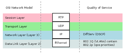
As you can see, on Layer 3 the QOS is DSCP while on Layer 2 is 802.1p. You can map the income Layer 3 TOS (DSCP) to a Layer 2 COS (802.1p). This can be used using the firewall mange rules; also it can be done from the bridge filter level.

[mepr-show rules=”319″ unauth=”message”]

Now if we want to implement QOS on Layer2, the old way was to use Queues (whether simple queue or queue tree). For this to make it work, we have to enable the setting “Use IP Firewall” under the bridge as you see below. By doing that, the created queues can work on the bridged traffic, but you will be using the CPU and HW-offloading should be disabled.

The other option is to use the bridge filter to mark packets then use parent=interface in the queue tree. Also, this option will use the CPU so we will have a higher CPU load on the switch and all Layer 2 frames will go through the CPU. This is not the best way to do QOS on Layer 2. For this reason, on the CRS3xx series there is a much better way to apply QOS while keeping Hardware-Offload.

If you go to the interface from the Switch Tab on Winbox, you will see a possibility to limit Ingress Rate and Egress Rate.

On the Ingress (incoming traffic), the CRS3xx will use policing. That means if the traffic is exceeding the threshold, it will drop the additional frames. On the Egress (outgoing traffic) it will use shaping that means it is nicer on the traffic compared to the policing one and will drop them but not as firm as on policing traffic.

This can be seen here:

As you can see, on Ether15 I am liming the ingress Rate to 3Mbps and Egress Rate to 2Mbps.

Let’s do a LAB to see if this will work.

LAB

I have SW1 and SW2 connected to each other on the Ether1 interfaces.

Let’s put the interfaces on a Bridge one and be sure that HW-offload is enabled.

We start with SW1:

We do the same on SW2:

Now both interfaces are in a bridge interface as each switch.

I would like to assign an IP address on Ether1 of SW1 of 192.168.0.1/24 and on Ether2 of SW2 of 192.168.0.2/24 so I can run Bandwidth-test and see how much traffic they can do without any limitation, then I will do a limitation on one of the switches.

Let’s start with SW1:

We do the same on SW2 and we put an IP address of 192.168.0.2/24 on interface Ether1.

Let’s do BW-test from SW2 to SW1 and see how much I will be getting on both upload and download as traffic.

To do that, you have to go to SW2 and from Tools you go to Bandwidth, finally you put the IP of SW1 with both directions and you click start:

As you can see, I am able to reach almost 100 Mbps on Tx and 820 Mbps on Rx.

Now, let’s apply the QOS on Layer 2 from SW1. I can only give 5 Mbps on ingress and 5 Mbps on egress. Then, we re-do the test and see the result.

So we have limited the ingress and egress traffic on Ether1 to be 5 Mbps on each direction.

Let’s do the BW-Test from SW2 again and see the result.

As you can see, it is not exceeding the 5 Mbps on each direction. So our configuration is correctly done.

[/mepr-show]

Course Content

0 Comments

Submit a Comment

Your email address will not be published. Required fields are marked *


The reCAPTCHA verification period has expired. Please reload the page.

About