The 1st type of VLAN that we have available on MikroTik Switches is Port-Based VLAN.
As its name mentions, the VLAN tag is added to the frame coming to the port of the switch using what we can “pvid”. This is exactly what we have seen up to now, when the frame comes to a port from an end device it will be tagged and when it leaves the port to an end device, it will be un-tagged.
Port-Based VLAN is one of the most common VLAN types used nowadays.
To configure Port-Based VLAN, it differs from one MikroTik Switch model to another. In this course, I will be focusing only on configuring MikroTik CRS3xx Switches.
MikroTik provides us with different ways to configure VLANs. However, the best way is to use the Bridge VLAN filter where all traffic will be hardware-offloaded which means that the traffic will not go to the CPU. However, to mention here, if you want that all your traffic to be hardware-offloaded, you should use only 1 bridge interface. In case you create 2 or more bridges, then interfaces that belong to the 2nd bridge will not be hardware offload but software ones, which means that the traffic will have to go to the CPU. Also, when using bridge VLAN filtering, we will profit from all other features that are available on the switch chip such as IGMP snooping, DHCP snooping, RSTP, MSTP, etc….
So now we understand what Port-Based VLAN is, let’s do a LAB so we can have more information on how to configure it on a CRS3xx series switch.
LAB: Port-Based VLAN
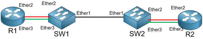
I have 2 CRS3xx series switches connected to each other on Ether1. On SW1 and SW2, Ether1 should be the trunk port and Ether2 and Ether3 should be the Access port in which Ether2 will be on VLAN20 and Ether3 on VLAN30.
Then I am going to create 2 DHCP servers on R1 on Ether2 and Ether3 and will see if Ether2 and Ether3 of R2 will receive IPs from the DHCP servers created on R1.
We will start by configuring the ports on SW1 and SW2 as Trunk and Access ports.
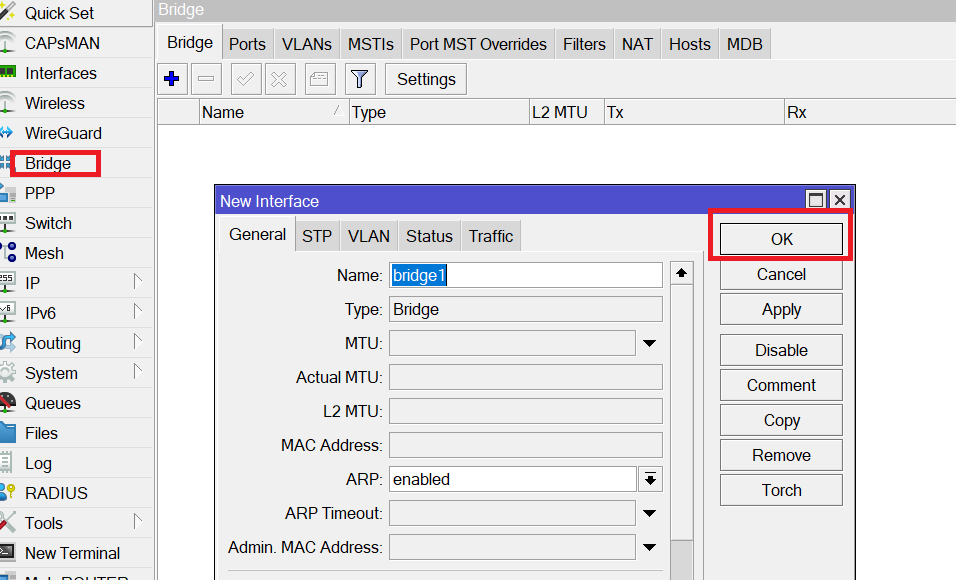
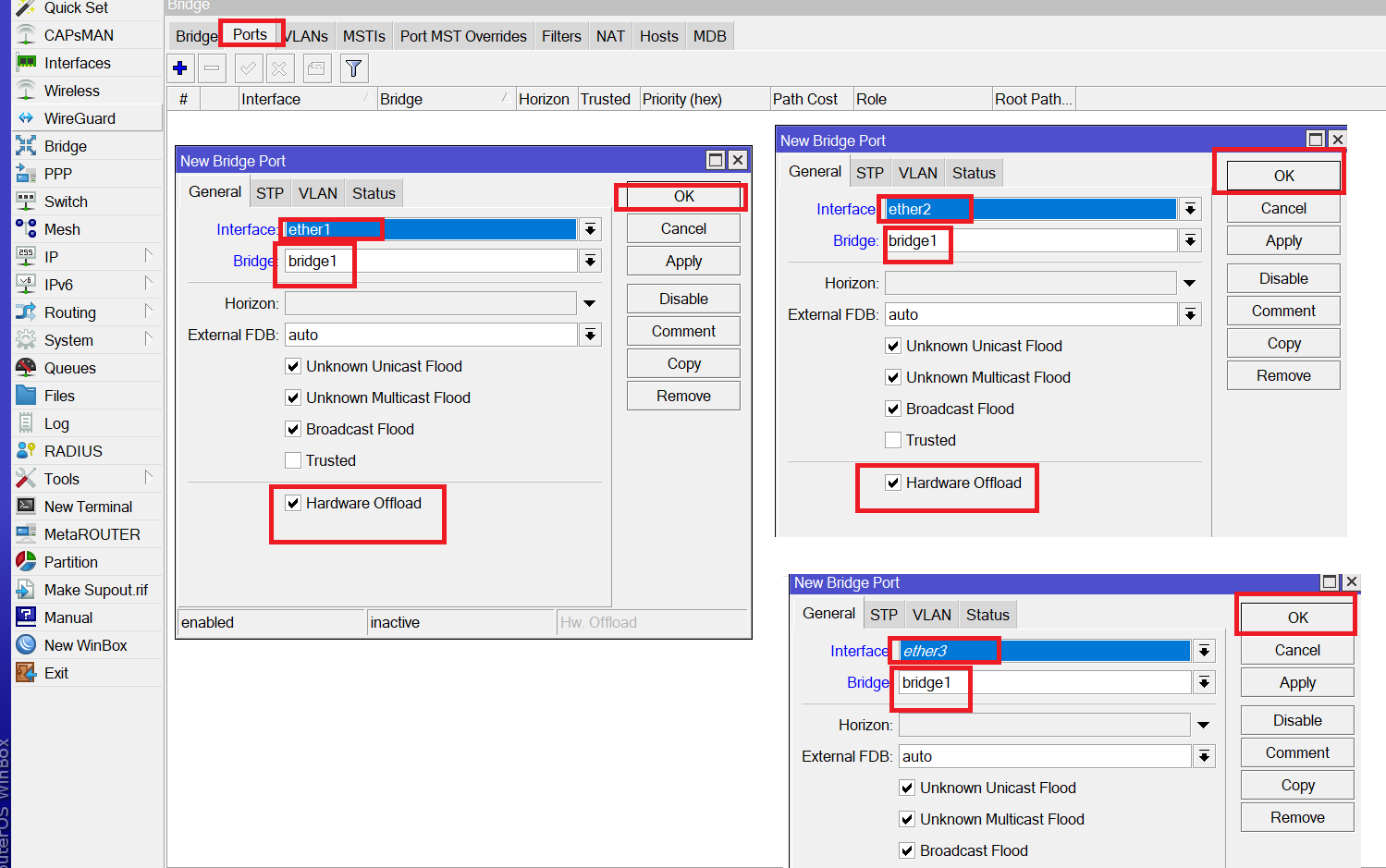
On both SW1, will create a bridge interface and put inside it Ether1, Ether2 and Ether3 (be sure that hardware offload is checked on all added interfaces)
Adding ports to the bridge interface on SW1
Apologies, the Full Lesson Access is Only for Members....

Get Access to all Lessons from different Vendors
Affordable Price to Enhance your IT Skills!
Always Accessing all Lessons including the New Added Ones

100% Satisfaction Guaranteed!
You can cancel your membership at anytime.
No Questions Asked Whatsover!
0 Comments