Understand and configure Multiple Spanning Tree Protocol (MSTP) on the MikroTik switches

Now we understand how STP and RSTP works, it is time to check the last type of STP protocol that is available in MikroTik CRS3xx Switches which is Multiple Spanning Tree Protocol (MSTP).

We use MSTP when we are using VLANs in our network. Let’s say that you in your network VLANs from 100 to 300. If you use RSTP, then all VLANs will be having 1 Spanning Tree instance with one Root Bridge. That means that all VLANs will not use the segment where the alternate port is. So we will end up like this:

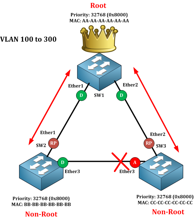
As you see, the segment between SW2 and SW3 will not be used by all VLANs. So imagine a total of 200 VLANs flowing on the same segments while we have 1 segment which is unused. Is there a solution for that? Yes, there is, we can use MSTP.

With MSTP you can create 2 or more instances, and you divide the VLANs based on the instances. Something like this:

  • MSTP instance 1: VLAN 100 to 200
  • MSTP instance 2: VLAN 201 to 300

So you have 2 instances which means 2 CPU instances. Then you say that for the instance 1 the root bridge will be SW1 for example and for instance 2 the root bridges will be SW2 for example. This way, the alternate port which is not used in instance 1 will be used on instance 2 and vice versa. Did you get the idea?

To mention that Cisco has something called Per-Vlan STP or Per-Vlan RSTP where the switch creates 1 instance for each VLAN. That means if you have 200 VLANs, then the Cisco switch will have to create 200 CPU instances, and that’s a wasting of resources, that’s why it is better to use MSTP where you can group many VLANs under one instance. On MikroTik, Per-VLAN STP and Per-VLAN RSTP are not available, so the Spanning-Tree works on port-based and not on VLAN-based.

Then, how will the scenario look when using MSTP?

[mepr-show rules=”319″ unauth=”message”]

As you can see, 2 instances have been created and for each instance we elected a Root bridge. This way the segment which wasn’t used in one instance will be used in the 2nd and vice versa.

Excellent!  So you have gotten the idea why we need to use MST on MikroTik CRS3xx series switches, let’s see now what we need to make as a configuration to make it work.

The first thing you need to do is to select the MSTP mode on all the switches. Secondly, you need to create a region name or more (depending on the size of switching network). The region name has to be the same on all MikroTik Switches. Thirdly, you need to create a region number which also should be the same on all switches. Moreover, you need to map the VLAN to the instances. For example, you say from VLAN 100 to 200, the instance is 2 and from VLAN 201 to 300 the instance is 3.

Also, you need to change the priority in the bridge ID under one instance so the root bridge for instance 3 is different than the root bridge of instance 2.

Briefly, we have to do the following:

  • Region name (should be identical on all switches)
  • Region number (should be identical on all switches)
  • VLAN mapping
  • Changing the bridge id for instance 3

Finally, it is mandatory to create the VLAN’s beforehand because MSTP is for VLAN’s, and you should have trunk ports between all switches.

Now let’s apply this on a LAB.

LAB: Multiple STP

I am still on the same LAB scenario, but I have created VLAN 10, 20, 30 and 40. I want VLAN 10 and 20 to be on an MSTP instance and VLAN 30 and 40 to be on another MSTP instance. Then I need to make the root bridge on the 2nd MSTP instance to be different than the one which is on the 1st MSTP instance, this way I can profit from using the segment which was un-used on the 1st MSTP instance.

First, the VLANs have to be created and make the switches’ interfaces connected to each other as a trunk port (in this LAB I will not show how to create VLANs because by now you should already know how this can be done).

Now we need to select the spanning-tree mode to be MSTP on all 3 switches. This is how you can do it on the 3 switches:

You may have noticed when you selected the MSTP protocol mode, the Region name and Region Revision have been enabled.

Now we need to put the Region name and Revision to be the same on the 3 switches. I am going to use the following:

  • Region name = Region
  • Region Revision = 1

Let’s apply this on the 3 switches like the following:

The last step would be to create the MST Identifier (MSTI) which is the instance as I have explained in the theory. I am going to create 2 MSTI as the following:

  • MSTI 2 for VLAN 10 and 20
  • MSTI 3 for VLAN 30 and 40

This needs to be created on each of the switches like the following:

So the MSTP has been configured correctly. Now we need to check which one of the switches will be the root bridge for instance 2 and instance 3. If we look at the LAB scenario, we see that SW1 has the lower bridge ID, so by the logic we should conclude that SW1 should be the root bridge from MST instance 2 and 3 because all priorities on the switches are the same and SW1 has a lower MAC address. Let’s check that to see if we are thinking correctly. I will check 1st for the identifier 2:

Indeed, it is the root bridge for the identifier 2.

Let’s check for the identifier 3 to see if SW1 is also the Root Bridge:

Also SW1 is the root bridge on the identifier 3. So our logic is correct.

Now, this is not exactly what we wanted. We wanted to use SW1 as the root bridge for identifier 2 but SW2 to be the root bridge for identifier 3. How can we do that? Let us go to SW2 and show you what we need to do.

As you see, from SW2 I moved to identifier 3 and I lowered the priority from 8000 to 7000. By doing that, SW2 becomes the root bridge on MSTI 3 because it has a lower bridge ID. Got it?

Let’s justify that on SW2 if it became the root bridge for MSTI 3.

Indeed, it became the root bridge on MSTI 3. That means all its port will be designated on MTSI 3. Let’s check:

You see that for identifier 3, all ports of SW2 are designated because he is a root bridge but on identifier 2 we have 1 root port meaning that SW2 isn’t the root bridge for identifier 2.

Let’s check now on SW1 who is the root bridge for identifier 2. Are all his ports designated on identifier 2?

Yes indeed, all ports on MSTI 2 are designated port that means SW1 is the root bridge for MSTI 2 as you can see in the picture below:

Finally, I am curious to know where the Alternate ports happen on MSTI 2 and MSTI 3 because I haven’t seen it on SW1 and SW2. It should be on SW3, correct?

Let’s check the port states on SW3 for both MSTI 2 and MSTI3:

As you can see, the Alternate ports are both on SW3. Ether3 is the alternate port on MSTI 2 and Ether2 is the alternate port on MSTI 3. Both are on 2 different segments, which mean that the alternate port on MSTI 2 is being used on MSTI 3 and vice versa.

Wow! That’s a really great LAB. This is all about MSTP and also about Spanning-Tree Protocol that you require knowing for the MTCSWE exam, I hope you enjoyed this chapter and I see you in the upcoming one.

[/mepr-show]

Course Content

0 Comments

Submit a Comment

Your email address will not be published. Required fields are marked *


The reCAPTCHA verification period has expired. Please reload the page.

About