In this chapter, I will talk about Link Aggregation on Switching or what we normally call Bonding on MikroTik.
The idea is very simple. If we have a scenario like this, then one of the interfaces will be on Alternate because of STP as we have redundancy:
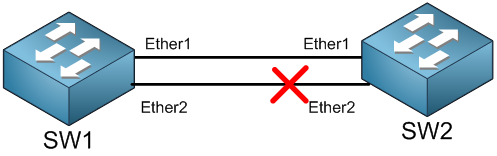
That means you are wasting a whole complete link because of STP. Of course, we want STP to keep running to avoid having loops, but we also want to use the 2 links at the same time. So what options do we have? That will be bonding.
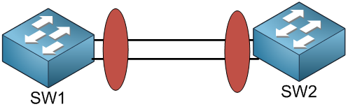
With bonding, you are grouping 2 or more switching links in which you will have a logical bonding interface and traffic can flow using the 2 interfaces together. When doing Bonding, the MikroTik switch will see the bonding interface as a normal interface and will apply STP on it, which means the STP will not be applied anymore on the member interfaces which are in the bonding one.
So we will end up having this scenario:
Bonding on MikroTik Switches has different modes, some of them use the hardware offload while others will use the software offload.
Below is a table showing the different modes of bonding on MikroTik CRS3xx switches:
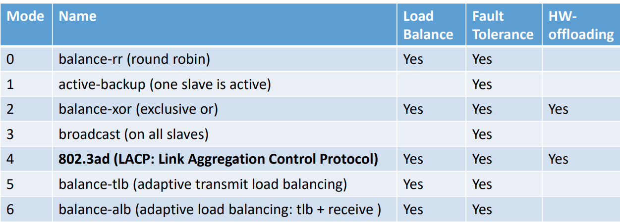
As you can see, there are 7 different bonding modes available on MikroTik Switches. For the MTCSWE course, you aren’t really responsible to know all details about each mode, but I am going to explain briefly each mode by itself.
Balance-rr mode: On this mode, there will be a round-robin load balancing. Slave interfaces in the bonding interface will transmit and receive data in sequential order. It will provide load balancing and fault tolerance.
Active Backup mode: This mode provides link backup. Only one slave can be active at a time. Another slave will become active only when the first one will fail.
Balance-xor mode: This mode balances outgoing traffic across the active ports based on the hashed protocol header information and accepts incoming traffic from any active port. The mode is very similar to LACP except that it is not standardized and works with layer-3-and-4 hash policy.
Broadcast mode: When ports are configured with broadcast mode, all slave ports transmit the same packets to the destination to provide fault tolerance. This mode does not provide load balancing.
802.3ad LACP mode: It is Open standard IEEE 802.3ad dynamic link aggregation. In this mode, the interfaces are aggregated in a group where each slave shares the same speed. Provides fault tolerance and load balancing. Slave selection for outgoing traffic is done according to the transmit-hash-policy. As in case of open standard protocol, this can be used on any vendor and the link aggregation will be formed without any problem.
Balance-tlb mode: Outgoing traffic is distributed according to the current load on each slave. Incoming traffic is not balanced and is received by the current slave. If receiving slave fails, then another slave takes the MAC to address the failed slave. This is mostly used on Linux servers running 2 or more NIC cards to make the bonding.
Balance-alb mode: It is an adaptive load balancing. The same as balance-tlb but received traffic is also balanced. The device driver should have support for changing its MAC address.
In this Unit, I will focus on the open standard and vendor neutral bonding mode which is 802.3ad or what we normally know it as LACP (Link Aggregation Control Protocol).
As briefly explained, 802.3ad mode is an IEEE standard also called LACP (Link Aggregation Control Protocol). It includes automatic configuration of the aggregates, so minimal configuration of the switch is needed. This standard also mandates that frames will be delivered in order and connections should not see disordering of packets. The standard also mandates that all devices in the aggregate must operate at the same speed and duplex mode (so you should be careful that you set the same speed and duplex modes on the connected switch interfaces).
LACP balances outgoing traffic across the active ports based on hashed protocol header information and accepts incoming traffic from any active port. The hash includes the Ethernet source and destination address and if available, the VLAN tag, and the IPv4/IPv6 source and destination address. How this is calculated depends on the transmit-hash-policy parameter.
When I do the LACP LAB configuration, you will see that there are 2 possible monitoring to use: ARP and MII.
What are those exactly?
As we are bonding 2 or more Layer 2 interfaces together, we need to monitor that if one of the links goes down then the switch will not send frame to it anymore. With ARP monitoring, it will send ARP queries and uses the response as an indication that the link is operational. If an ARP reply is received from the other interface, then the switch knows that the link is operational and will keep sending the traffic from it. RouterOS sets the arp-interval to 100ms by default, but you can change it if you want.
MII monitoring has the similar function as ARP, however, it will monitor the state of the local interface only, so when the interface is down the switch knows that the link is down and when the interface is up the switch knows that the link is up.
The switch driver should support MII in order to use it otherwise if it is not supported and MII is used then the link will always be shown up even when it will be down.
Now back to 802.3ad mode, the ARP link monitoring is not recommended, because the ARP replies might arrive only on one slave port due to transmit hash policy on the LACP peer device. This can result in unbalanced transmitted traffic, so MII link monitoring is the recommended option.
Enough theory, let’s apply a LAB for the Link Aggregation.
0 Comments