Virtual Local Area Network, or what we normally call it VLAN, is the main topic of the MikroTik MTCSWE course. VLAN is widely used in our networks, and this can be seen not only when using MikroTik Switches but also when using any other vendor switches like Cisco, Ubiquiti, Juniper, and so on.
The main question to be asked is: why do we need to use VLAN in our switching network? The answer is just so easy. Imagine you do not use VLAN in your network, then your network is called a flat network which means that in case 1 device does a broadcast, then all other devices will receive it, and yeah: Broadcast stops your network.
For this reason, we require a better design to segment our network in a better way using VLANs.
When you create 2 VLANs, for example, you put 1 device in each VLAN, then even though they are physically connected to the same switch, the connected devices do not see each other. That means they will not be able to communicate with each other and that’s the beauty of the VLAN.
In which scenarios you may need VLAN’s?
Imagine you have a small company with 3 different departments, then you can create 1 VLAN for each department. In this case, employees working in the same department can communicate with each other but not with employees working in other departments.
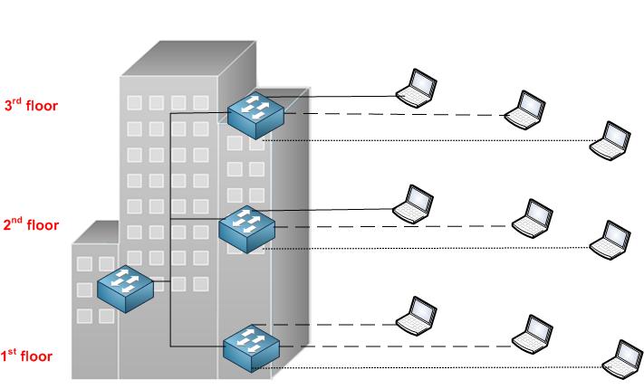 A company with 3 different department without using VLAN’s.
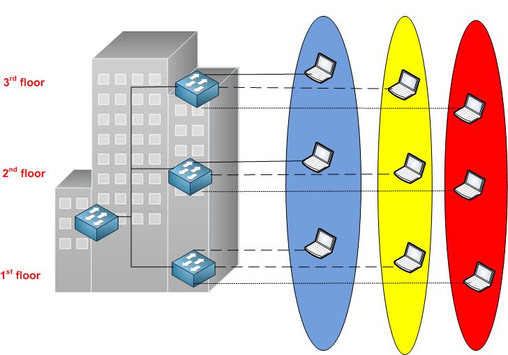 A company with 3 different department using VLAN’s.
Another example is to create a VLAN for IP phones which is separated from normal PC traffics that are on another VLAN. In this way, all traffic for the IP Phones will have a VLAN tagging which you can use to apply for it QOS and prioritize it in front of other traffic.
Another example as well is for ISP’s and WISP’s. They use VLAN’s to separate their customers from each other in a way that for each customer they assign a VLAN. That’s a very common way that most ISPs in the world use when they provide internet service to their customers.
What are the terminologies to know for the VLANs implementation?
When speaking about VLANs, they are terminologies that we should be aware of.
The terminologies are:
- Ingress: When the frame enters the switch coming from the end device
- Egress: When the frame exits the switch going to an end device or another switch
- Tagged: the frame has a VLAN tag or is tagged when forwarded
- Un-Tagged: The VLAN tag is removed from the frame when forwarded.
- Access port: Switch port connected to an end device where the tag is removed from the frame when it leaves the switch port interface toward the end device and the tag is added on the ingress.
- Trunk port: Normally used between 2 connected switches to allow more than 1 VLAN traffic to go from one switch to another.
Let me show you with an example: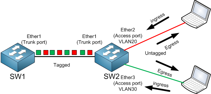
As you can see, SW1 has a Trunk port on Ether1 so it can receive the frames from different VLANs from SW2. That’s why it is tagged; same Ether1 of SW2. You can see that Ether2 and Ether3 on SW2 are connected to end devices, that’s why they are access ports. Once the frame comes inside Ether2, this is called ingress, then SW2 will give it a tag of VLAN20 and will send it from its trunk port Ether1 to SW1. Now if the frame is leaving out from Ether2, that’s the egress, the Switch will remove the Tag from it and forward it to the PC. Same if we look for Ether3 as well.
So now we understand how the VLAN works and what are the terminologies that we need to know, let’s see where the Tag appeared in the frame.
802.1Q VLAN Overview
The tag is nothing more than something added to the Ethernet frame saying that it belongs to a VLAN. You have to think of it like a mark or a color that the switch will understand that this frame belongs to a particular VLAN.
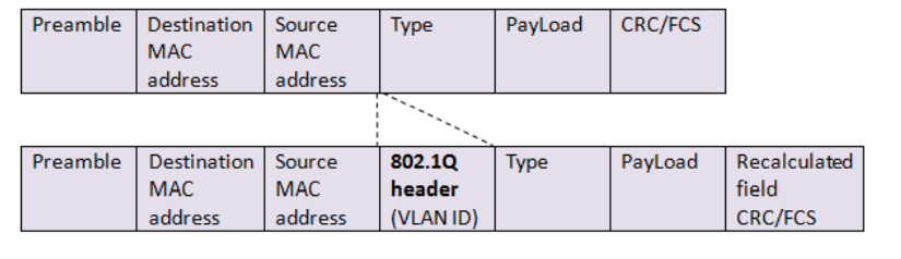
On top, it shows the normal Ethernet frame. Below you see when the frame has added the 802.1Q header which has the VLAN ID inside of it – that’s the tagging. You will see that the frame will remain the same but only a header has been inserted between the Source Mac address and the Type. This header contains a lot of information, and one of them is the VLAN ID.
Let’s dig inside more and see what this 802.1Q header contains: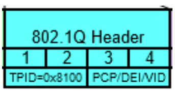
As you can see, the 801.1Q header (which is an open standard protocol) consists of many things.
- Tag protocol identifier (TPID)
- A 16-bit field set to a value of 0x8100
- Identifies the frame as an IEEE 802.1Q-tagged frame.
- Tag control information (TCI)
- Priority code point (PCP)
- 3-bit field which refers to the IEEE 802.1p class of service
- Drop eligible indicator (DEI)
- 1-bit field.
- VLAN identifier (VID)
- 12-bit field specifying the VLAN to which the frame belongs. (212=4096)
- VLAN IDs should not be used in generic VLAN setups: 0, 1, 4095
- Priority code point (PCP)
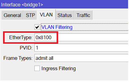
Let me explain this a bit. The TPID mentions whether you are using normal 802.1Q encapsulation or you are using Q-in-Q (will speak about Q-in-Q in this chapter). When you say the TPID value of 0x8100, then you are using normal 802.1Q encapsulation. That’s something you see inside the bridge in the MikroTik Switch configuration:
Then you have the Tag control information (TCI) which has inside of it:
- Priority code point (PCP)
- Drop eligible indicator (DEI)
- VLAN identifier (VID)
The PCP is used for the QOS on VLANs or what we normally call Class of Service (COS). The PCP consists of 3 bits, which means the priority which we can use starts from 0 to 7.
0 is the default one, while 1 is the highest priority and 7 is the lowest one.
For example, if you want to prioritize the ICMP traffic, you can use COS = 1. This can be done using the mangle rule or the bridge filter rules (I recommend using the bridge filter rule).
DEI consists of 1 bit and (formerly CFI[b]) may be used separately or in conjunction with PCP to indicate frames eligible to be dropped in the presence of congestion.
VID consists of 12 bits and that’s where the tagging happens. As being 12 bits, that means in each switch you can use up to 4096 VLAN. Why that, because 212 = 4096. The VLANS will start from 0, 1, until 4095. It is highly required to not use VLAN 0, VLAN 1 and VLAN 4095.
Excellent!!!! So now we have more information about the VLAN, let’s see the different types of VLANs we have on the MikroTik Switches.
0 Comments