Port isolation is a process in which you isolate a port (or group of ports) from another port (or group of ports). This means that the end device which is connected to one port will not be able to communicate with the end device connected to the other port.
Port Isolation is mostly used when you have a company having only 1 MikroTik CRS3xx switch. So instead of going through VLAN to segment the Layer2 network, you can use port isolation which is much easier to be configured and works perfectly.
On MikroTik CRS3xx, port isolation is available on the switch chip since RouterOS v6.43, which means it is hardware-offloaded and it doesn’t go to the CPU.
There are 2 different scenarios where you can use port isolation which is:
- Isolated Switch Groups
- Private VLAN
Both have the same idea as explained. But let’s start with the Isolated Switch Groups and do a LAB for it.
Isolated Switch Groups:
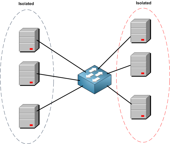
As you can see, I am grouping ports on the switch where it is possible for the devices to communicate with each other, but they cannot communicate with the other group.
Bear in mind that STP (when used) is not aware of the underlying port isolation configuration, therefore there are no separate spanning trees for each isolated network instead there is a single one for all isolated networks. This can cause some unwanted behavior (e.g. devices on isolated ports might select a root bridge from a different isolated network). That’s why I highly recommend using port isolation in case of only 1 Switch scenario and not more.
Another important notion is to remember to have HW-offload enabled on the ports that you want to use in the port isolation because if HW-offload is disabled then port isolation will not work and the RouterOS will not notify you about this.
Let’s move to the LAB now.
LAB: Port Isolation
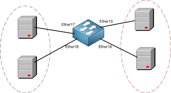
As you can see, the plan is to isolate 2 ports from each side, so Ether15 and Ether16 can communicate to each other but not to Ether17 and Ether18. Same will be done on the other side.
Let’s see how this can be applied.
1st we need to add all those ports to a bridge, and we should be sure that the HW-offload is enabled. I am sure by now you know how to add the ports to the bridge, so I will not show it again but here is the end result:
Apologies, the Full Lesson Access is Only for Members....

Get Access to all Lessons from different Vendors
Affordable Price to Enhance your IT Skills!
Always Accessing all Lessons including the New Added Ones

100% Satisfaction Guaranteed!
You can cancel your membership at anytime.
No Questions Asked Whatsover!
0 Comments