In this chapter, I am going to speak about Spanning Tree Protocol, which we normally refer to it as STP.
The STP protocol has 1 function on our layer 2 network: it is to avoid having loops on layer 2.
What’s the meaning of loop exactly and how it happens? Let me show you with example:
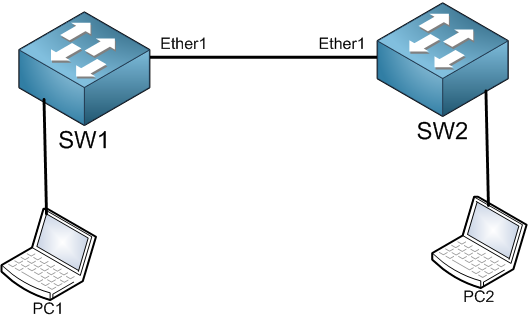
In this scenario, we have 2 switches connected to each other with 1 cable. We do have one point of failure because in case the cable or any of the connected ports is damaged, then our network goes down. To get rid of the single point of failure, we will have to put another cable as following:
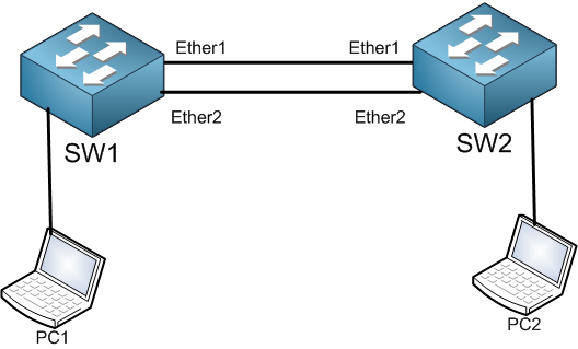
When adding the 2nd cable, we will have redundancy. That’s a good thing. But the bad thing is that with redundancy we will end up having loops.
Let me show you how the loop can happen in this scenario.
- If PC1 sends an ARP request to get the MAC address of PC2, then PC1 will send a broadcast frame.
- SW1 will receive the broadcast and will send it to all its ports except the port from which the ARP request came. So, he will send it from Ether1 and Ether2.
- SW2 will receive the broadcast frame from Ehter1 and from Ether2.
- In its turn, SW2 will send the broadcast from all ports except the port that the frame came in. That means it will send the broadcast that came from Ether1 to Ether2 and the PC2, and the frame that came from Ether2 to Ether1 and PC2.
- SW1 will receive the broadcast frames again from Ether1 and Ether2 and will do the same as SW2 did.
This will keep moving like this for an indefinite time. That means nothing will stop the loop and when it happens, then your network is down. I have received a lot of questions from my students saying that TTL (Time to Live) is the time that the Ethernet frame has before it dies, which solves the problem. My answer is always that TTL is for Layer3 packets but not for Layer2 frames. On Layer2 there is no TTL, which means the loop will never end. In this case, the only solution we have is to remove one of the cables from the 2 switches then the loop is over but we will not have redundancy anymore, or we apply STP while keeping both cables connected.
How spanning-tree solves the problem
With STP, we will have a loop-free topology on Layer2. To understand STP better, I will go to examples. Let’s say we have the following scenario:
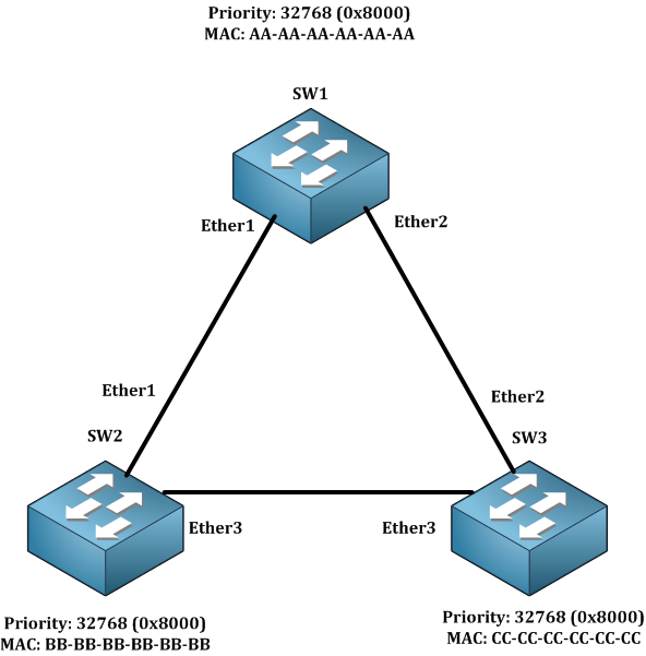
As you can see, we have 3 switches connected to each other, and we do have redundancy here. Why do we have redundancy? If you take SW2, it can reach SW3 directly from Ether3 but it can also reach it from SW1. That’s what redundancy is. Again remember, when we have redundancy, we have loops. So how to avoid it? We need to run STP.
As you can see in the picture, each switch has a priority and a MAC address. By default, all priorities on the CRS3xx switches are the same. MikroTik uses the priority on Hexadecimal which is 0x8000 (equal to 32768 on decimal).
If STP is enabled, the switches will send to each other a special frame called BPDU (Bridge Protocol Data Unit). This special frame has 2 information’s that STP requires:
- MAC Address
- Priority
The Mac address and the priority together make what we called the Bridge ID.
Let’s see how the BPDU’s will be sent:
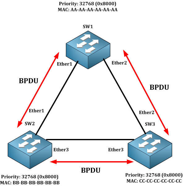
Why are the BPDUs sent from one switch to another? Because they need the bridge ID to elect the switch which is going to be the root bridge.
The switch which has the lower bridge ID (Priority + MAC) will end up being the root bridge. Look at the picture above, which switch has the lowest bridge ID? You see that all have the same priority, then we look at the MAC Address. If we see that SW1 has the lowest MAC address between all, then SW1 will end up being the root bridge.
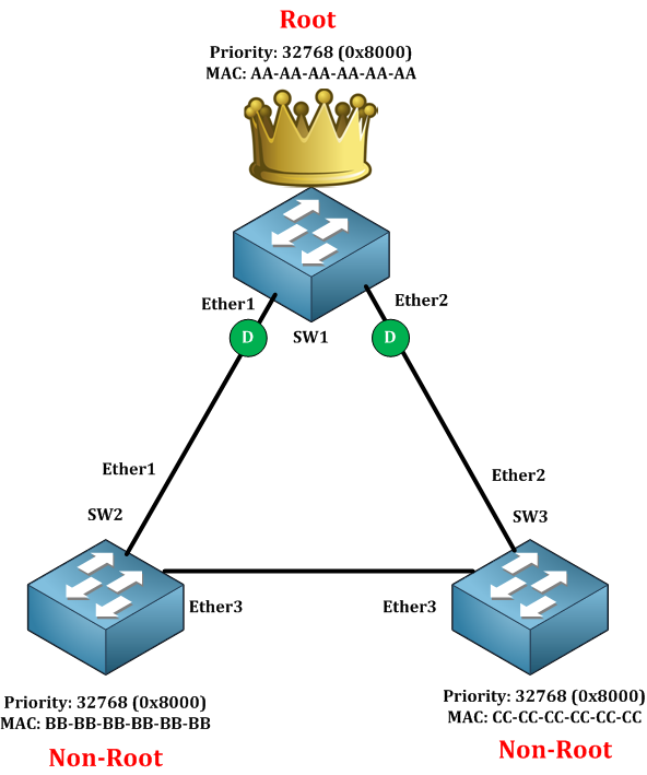
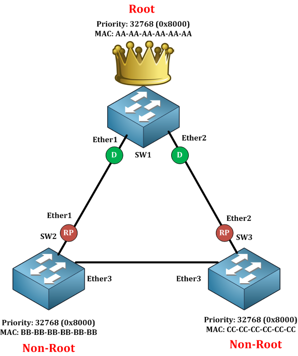
As you can see, SW1 has become the root bridge and directly all the ports of the root bridge move to the designated state, which means they can forward the traffic. SW2 and SW3 became the Non-Root bridges. Those non-root bridges will check what is the shortest path for them to reach the root bridge. On SW2, the shortest path to reach SW1 is to go from the Ether1 interface and for SW3 the shortest path to reach SW1 is to go from Ether2. Then those ports are called Root ports. Of course, you can change this by changing the cost of the interface but let’s assume that we have the default cost which is 10 on all interfaces that means our scenario will become like this:
On root port, the traffic will be forward also. So that means until now we haven’t solved the loop issue because all ports are still forwarding whether they are designated ports or root ports.
We will have to look at the last segment which is between SW2 and SW3. One of the ports should go to a blocking state (also called Alternate) which means that it doesn’t pass traffic. Again, both switches (SW2 and SW3) will compare their Bridge ID and the one which has the lower Bridge ID will go to Designated and the other will go to Alternate. We see that SW2 has the lowest bridge ID, then that’s how the scenario will end up:
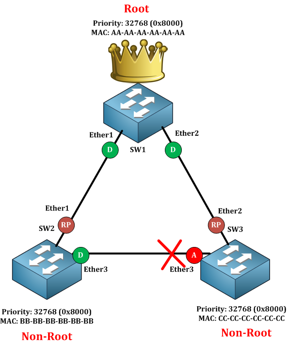
Now, why did Ether3 of SW2 become a Designated port and not a RP for example? Well, because you require 1 Designated port on each segment. You see that on each of the segments there is 1 Designated port. Now we do have a loop-free topology because Ether3 of SW3 is not allowing traffic to pass. But what if any of the operational links go down? In this case, the Alternate port will move to a forward state, and that’s exactly what the main job of the redundancy network is.
Let’s say that the network is working now and all of sudden port Ether1 of SW1 goes down, then the alternate port has to move to a forward state. How long does this take for the failover to happen? Let me show you:
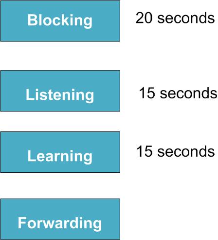
As you see, it may take up to 50 seconds for the failover to happen. I know this is a long time to wait to have our network operational again. Remember, STP is a very old protocol that was made in the year 1983, so in that time 50 seconds was not a big issue for the failover to happen. As for now, we can’t wait that long and that’s why we have Rapid-STP which is an enhanced STP protocol and which works much faster (we will start to learn about RSTP in this course).
Back to the scenario, the port on the blocking state will wait up to 20 seconds to move to the listening state. When in listening state, the port will start receiving and sending BPDU’s but do not learn MAC address nor transmit data. The listening state takes up to 15 seconds.
One on learning state, the port will still send and receive BPDU’s and will learn MAC addresses but still does not transmit data. This state takes up to 15 seconds.
Once on the forwarding state, the port will start transmitting data.
This is the whole process of the transition of the port from Alternate to forwarding.
Enough of theory, let’s apply the first LAB about STP.
0 Comments