Q-in-Q, which is also referred to as 802.1ad, is to send a VLAN tag inside another VLAN tag. But why we do need to do that?
Well, there are many reasons for that. The 1st reason is that in case we need to use more than 4096 VLAN in our network, then this is not possible as we have seen. When using Q-in-Q you can have the possibility of increasing the number of VLANs.
In most cases you can use Q-in-Q in an ISP network from which a company has a VLAN from its provider and wants to distribute internet service to different customers putting each one of them on a separated VLAN. Then in this case you require to use Q-in-Q. Or maybe you have a reseller for your ISP and this reseller is assigned to a VLAN, and he wants to put each of his customer on a different VLAN then you can use Q-in-Q (the list of examples can go longer).
When we used normal VLAN, we set the Ethertype to be 0x8100. For Q-in-Q, the Ethertype should be 0x88A8 which is also referred to as SVID.
It’s very important to remember that each time you use Q-in-Q, then MTU will increase, so be sure that you have an L2 MTU that is big enough to support the Q-in-Q frame.
The last thing that I want to say here is why we call it Q-in-Q. The answer is very easy. We are doing 802.1Q encapsulation inside and 801.1Q encapsulation. Which means a VLAN inside a VLAN. That’s why it is called Q-in-Q which refers to the 801.1Q. Does this mean that if we intercept the Q-in-Q traffic we will see 2 VLAN tags? The answer is yes, we will.
Enough speaking about Q-in-Q, let’s apply the LAB now.
LAB: Q-in-Q
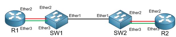
The LAB is still the same as we have left it in the previous one. What I need to do is to create on R1 VLAN22 on Ether2 and VLAN33 on Ether3 and to have the DHCP servers on them. In this case, I have VLAN’s on R1 different than what is on Ether2 and Ether3 of SW1. We will see if the VLAN22 and VLAN 33 will be able to reach the DHCP client on R2 when using Q-in-Q.
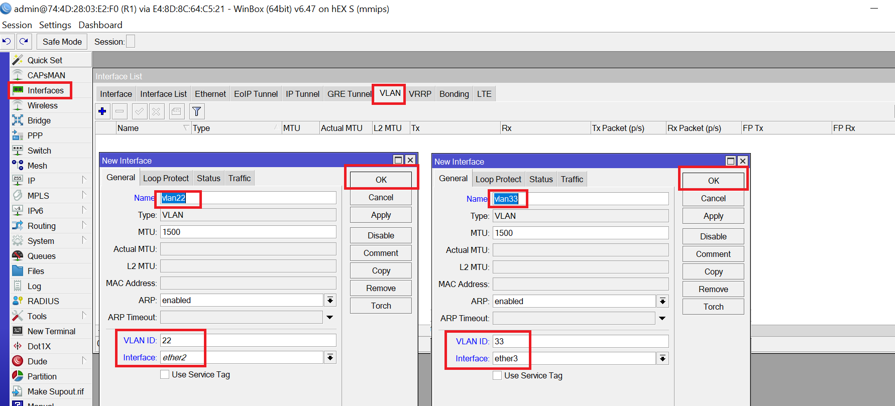
Let’s go to R1, create VLAN 22 and VLAN 33 then move the DHCP server to them:
Apologies, the Full Lesson Access is Only for Members....

Get Access to all Lessons from different Vendors
Affordable Price to Enhance your IT Skills!
Always Accessing all Lessons including the New Added Ones

100% Satisfaction Guaranteed!
You can cancel your membership at anytime.
No Questions Asked Whatsover!
0 Comments